If cool down heated temperature of a fluid when air or gas compress, heat exchanger efficiency shall be increased by its high density.
Intercooler for Compressor
Fluid name: air to water
Design pressure: 125bar at 150℃
Material: C7060T
After Cooler
Fluid name: cooling water to air
Material: SUS304L
In/After Cooler
Fluid name: air to water
Design pressure: 10bar at 150℃
Material: C1220T
Inter Cooler
Fluid name: air to water
Design pressure: 21bar at 150℃
Material: C1220P
In/After Cooler
Fluid name: air to steam
Design pressure: 15bar at 180℃
Material: C1220T
In/After Cooler
Fluid name: air to water
Design pressure: 10bar at 150℃
Material: STS304TB
Inter Cooler
Fluid name: air to water
Design pressure: 10bar at 160℃
Material: C1220R
H2 Cooler
Fluid name: water to water
Design pressure: 525bar at 200℃
Material: STS304TP-S
Inter Cooler
Fluid name: air to cooling water
Design pressure: 9.9kg/cm² at 160℃
Material: A240-304
Gas Cooler
Fluid name: gas to water
Design pressure: 1.06MPa at 250℃
Material: C.S
Comp- Cooler (Blazing)
Fluid name: air to cooling water
Design pressure: 6.8kg/cm² at 105℃
Material: C7060T, C1220R
4 Stage Inter Cooler
Fluid name: air to cooling water
Design pressure: 16kg/cm² at 150℃
Material: SUS304
Inter Cooler
Fluid name: air to cooling water
Design pressure: 10.5kg/cm² at 150℃
Material: SUS304S, A516-70
1ST Inter Cooler
Fluid name: air to water
Design pressure: 16.8kg/cm² at 65℃
Material: C7060T, A1100P
After Cooler Bundle & Separator
Fluid name: cooling water to air
Design pressure: 0.97MPa at 160℃
Material: C1220T, SUS304, SS400
Final Cooler
Fluid name: gas to water
Design pressure: 5.5bar at 280℃
Material: SUS304TB, C.S
EGR Cooler
Fluid name: gas to water
Design pressure: 10bar at 625℃
Material: SUS304, C.S
After Cooler Bundle
Fluid name: cooling water to air
Design pressure: 10kg/cm²
Material: SUS304L
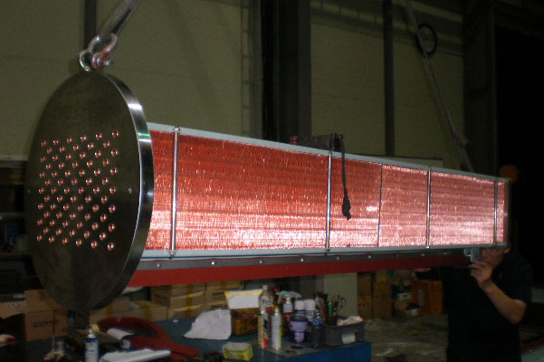
COOLER
Compressor Cooler
If cool down heated temperature of a fluid when air or gas compress, heat exchanger efficiency shall be increased by its high density.
structure
Heat Exchange Flow Diagram
specification
Capacity of Heat Exchanger
The heat exchange amount of the heat exchanger is determined by the circulating amount of the heat medium circulating, the circulating amount of the exchange fluid, the heat transfer area and the heat transfer speed of the heat exchanger, and the average water temperature difference between the two exchange fluids.
Q = U × A × ΔT
Q Heat exchanged = kcal/hr
A (Heat transfer area) = the indirect contact area of the two fluids being heat exchanged m2
U Overall heat transfer coefficient: kcal/㎡-hr-℃
The amount of heat exchanged for 1 hr at the indirect contact surface per 1 ℃ of temperature deviation (ΔT) per 1 m2 of the heat transfer area of the heat exchanger
It depends on the heat conduction of the metal material constituting the heat exchanger and depends on the characteristics of the exchanged fluid.
ΔT = average temperature difference (Δ℃)
Units used in heat exchanger design – Calorie 1kcal/h = 1.163W 1 W = 0.86 kcal/h 1kW = 860 kcal/h 1usRT = 3,024 kcal/h – Heat flux 1kcal/m2/h = 1.163 W/m2 1W/m2 = 0.86 kcal/m2-h
specification
Tube to Tubesheet Joint
Expansion – Design temperature less than 400℃ Design pressure 20kg/㎠ or less
2 or more GROOVEs – Limited to design pressure 20kg/cm2 or design temperature 175℃ or higher
Expansion + SEAL welding – When the fluid easily leaks even at the design temperature of 400℃ or less When the design pressure is 60kg/cm2 or more
STRENGTH WELDING – When the design temperature is 400℃ or higher, or when sufficient strength is required for the connection part
specification
Recommended Velocity for Tube inside
Tubeside velocity range for treated / fresh cooling water velocity shall be as follows :